
-
1 Introduction
-
2 Theoretical concepts
-
3 The printing process
-
4 Arm assembly and electronics
3D printing. Printing the parts
Know how to generate a 3D part from an STL file. Monitor the process and verify its achievement.
The first thing you have to do is download all the STL files that you are going to print and evaluate the files that are going to be printed before or after. You have to keep in mind that a large file like the base will take a long time to print so it is a good idea to leave it printing for after school or at night. Smaller pieces can be printed during classes.
Advice: it is recommended to verify the first minutes of printing as they are the most critical since the piece may lose adherence or generate warping.
As many pieces have to be printed, a round-robin system has been chosen among the students so that each and every one will print a piece of the arm.
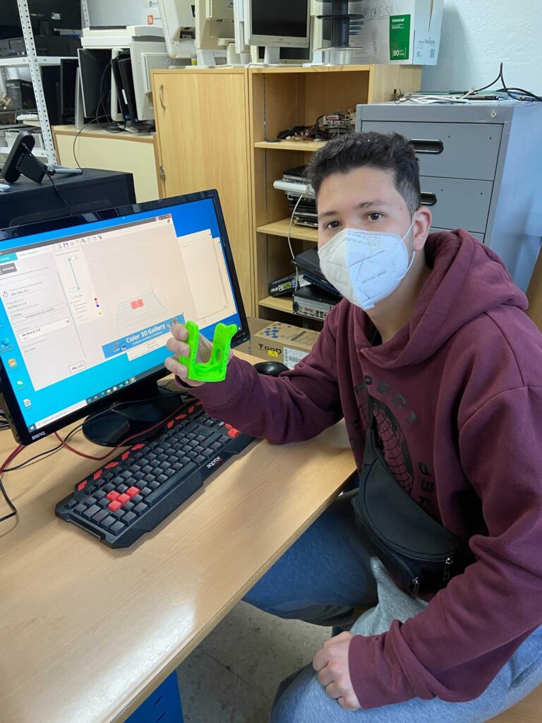
The goal is for each student to print a piece from scratch choosing the STL file, the printing parameters, etc. And be in charge from the time the piece is sent to printer until the print job is finished.
The student must take care that the base has a sufficient proportion of fixing lacquer and, above all, will be aware of the most critical phases of printing, such as the start and end of it when the height is considerable.
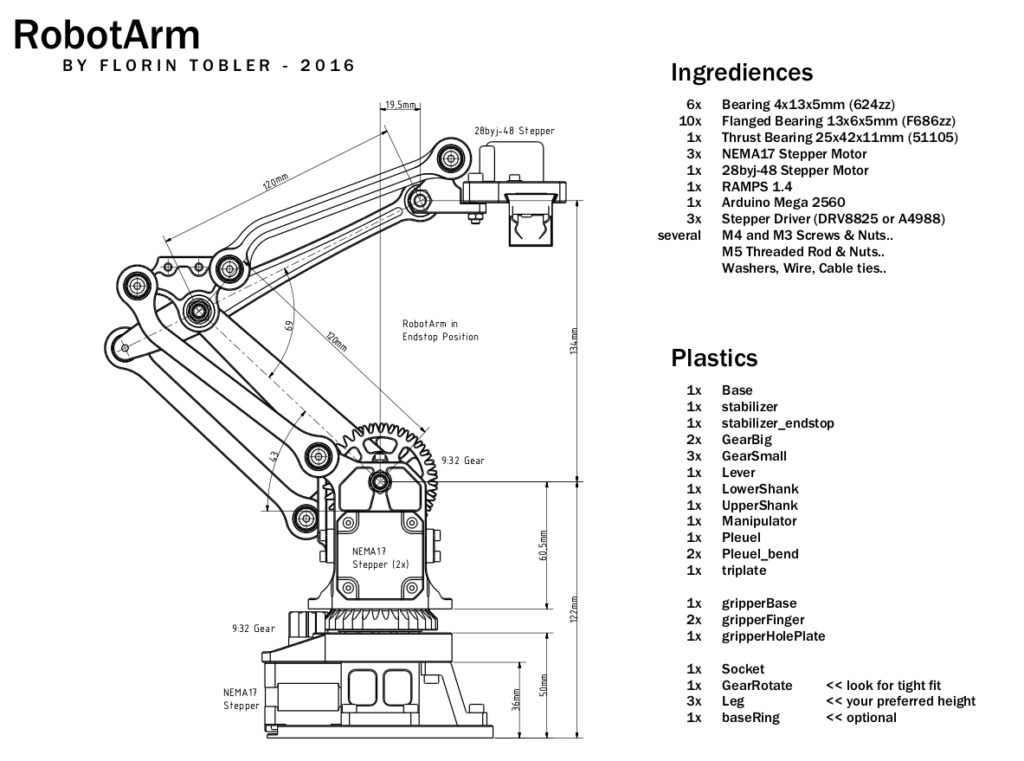
As you can see in the figure above, the arm will have many plastic parts in addition to other electronic and mechanical parts like motors, nuts, arduino board, RAMPS, etc.
The pieces to be printed are listed in the following figure:

Before printing, the part has to be visualized in a specific 3D visualization program to determine the best position of the part to be printed.
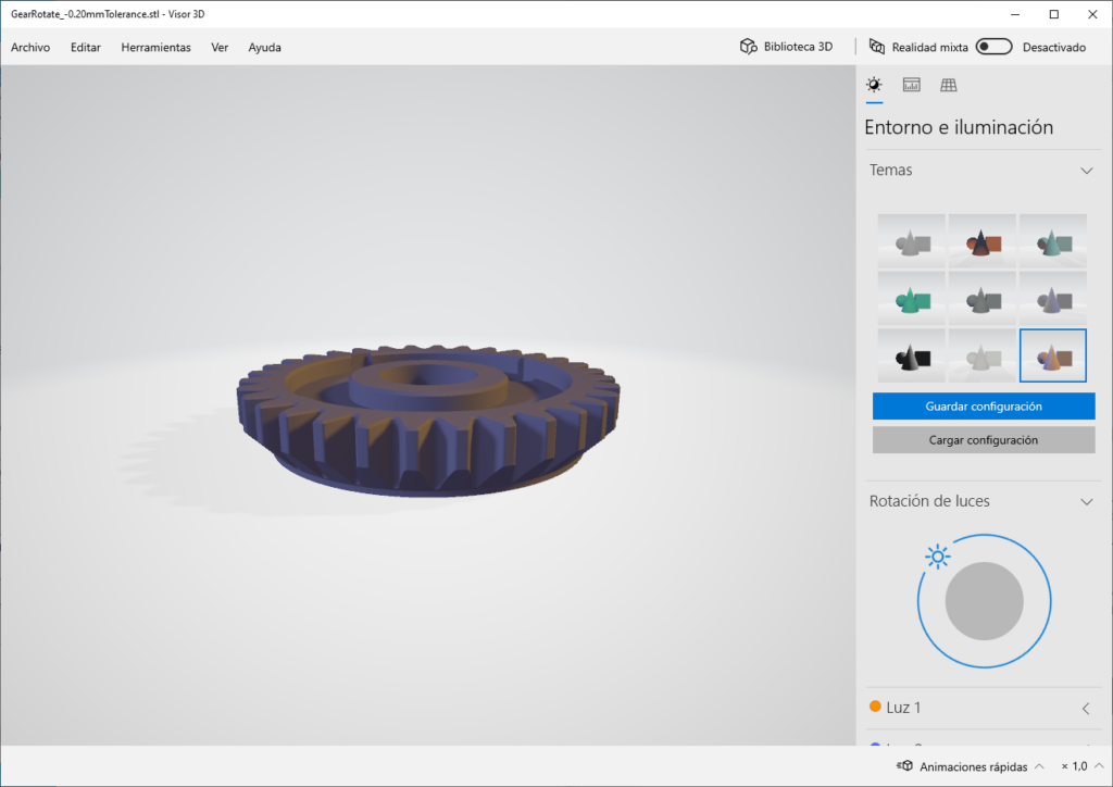
With a 3D viewing program, the piece can be viewed from different positions and focused with lights from different angles. In this way the geometry can be visualized in a complete way.
Generally, the position of the pieces is usually adequate for printing, but nevertheless the student has to assess this fact since when creating or designing a piece, the position it takes on the printing bed is important.
Activity for learning about design 3D parts
In order for the student to know the whole process from the moment a design is created until it is finally printed and is involved in the retouching process, the following activity has been created:
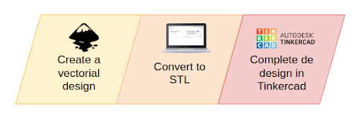
In the first step of the activity, a vector image will be created using a tool such as Inkscape. Inkscape is a free and open source vector graphics editor. Inkscape (https://inkscape.org/) can create and edit complex diagrams, lines, graphics, logos, and illustrations. The main format used by the program is Scalable Vector Graphics (SVG).
We have created the logo for our project with this tool:
![]()
The SVG format, which is a vector format, will allow us to transform it into an STL format. For this you can use online converters such as svg2stl.com, anyconv.com, etc. It is not necessary to install any extra software on the computer to carry out the transformation.
With the tinkercad application, many transformations can be done in a simple way and without having knowledge of designing.
For example, we have decided to add a base to the design so that when printing there are no warping problems.
![]()
Once the STL design has been created, the generated file will be transformed into gcode or the program that uses the 3D printer. This last step will depend on the printer being used.
By evaluating the work done